Controlled drawing or CAD
Send PDF, DWG or STEP with revision, critical surfaces, workpiece material, forming operation and the mating casing or holder. Mark the features that govern fit or material flow.

Custom forming-tool route
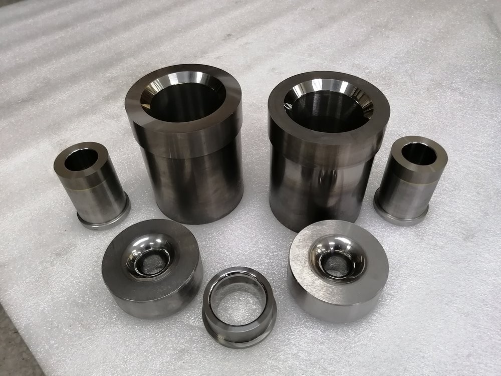
Carbidea makes custom tungsten carbide dies and mold components for cold-heading, stamping, compaction and metal-forming toolmakers. Send a PDF, DWG or STEP drawing, or a worn sample with operating conditions. We cover drawing, extrusion, powder-compaction, ironing and slitting types, support small batches, and quote in 1–2 business days.
01 / Input record
The part print defines geometry. The operation defines why that geometry is stressed: impact, strip clearance, wall reduction, powder ejection, edge shear or an orienting magnetic field. Review both together before selecting a material or assembly direction.
Send PDF, DWG or STEP with revision, critical surfaces, workpiece material, forming operation and the mating casing or holder. Mark the features that govern fit or material flow.
Send scaled overview and close-up photos, the mating assembly and the failure location. State whether the part cracked, galled, chipped, lost its edge, changed fit or caused magnetic interference.
Finished profile, shoulder radii, lead-in, working land and controlled bore or edge.
Workpiece, reduction or stroke, lubricant, ejection condition and previous failure.
Stress ring, casing, retainer, spacer stack or mating punch and the intended fit.
02 / Die & mold type register
This is a review map, not a fixed catalogue. Material direction and manufacturability are evaluated against the drawing and operating record.
| Component / route | Failure to control | What the review checks | Material direction |
|---|---|---|---|
| Cold-heading die insert / punch | Longitudinal split, impact fatigue, bore galling | Wire grade, reduction, entry lead-in, stress ring and EDM finish | Tough WC-Co direction |
| Stamping punch / die insert / bushing | Edge chipping, spalling, fatigue and strip galling | Compound, progressive or transfer architecture; clearance, support and stripping | Toughness / wear balance by station |
| Ironing or redraw die | Aluminum pickup, axial scoring, ringing wear and radial fatigue | Reduction stage, lubricant, polish direction, casing and final sizing sequence | Fine-grain WC-Co direction |
| Drawing die / mandrel | Inlet wear, bell-mouthing, galling and profile loss | Pass schedule, entry angle, bearing length, finish and support | Wear / toughness balance |
| Extrusion die / nib | Nib fracture, bearing galling and recast cracking | Deformation ratio, bearing length, support condition and corner radii | Impact-resistant WC-Co direction |
| Powder-compaction die liner / punch | Axial galling, edge chipping and radial burst | Powder, ejection force, polish orientation, pre-stress rings and EDM removal | Fine-grain WC-Co direction |
| Slitter or rotary cutting knife | Edge chipping, rounding, burr and axial wobble | Foil or sheet, clearance, edge preparation, runout and spacer stack | Micrograin WC-Co direction |
| Non-magnetic die / punch / liner | Magnetic interference, powder pickup, EDM micro-cracking and edge chipping | Target permeability and test method, orienting field, powder, impact and finishing | WC-Ni / WC-Ni-Cr direction |
Capability, tolerance and minimum quantity are assessed part by part. No universal tolerance, tool life or batch level is implied by this register.
03 / Failure & control
Failure evidence changes the route: a tougher grade alone does not correct a bad shrink fit, an untreated EDM surface or a polish direction that traps material.
Review corner radii, punch support, strip clearance and the balance between wear resistance and toughness.
Review binder direction, surface finish, polishing direction, lubricant and the sliding or ejection route.
Review the carbide / steel assembly, stress rings, interference intent and the sequence of shrink fitting.
Plan removal of the affected wire-EDM layer and finish critical working surfaces after assembly where the sequence requires it.
Match grain and binder direction to the workpiece, pressure and wear path; define the working land that must remain.
Review the nickel-binder route against the stated permeability target and test method, then control powder pickup and EDM condition.
GENERIC ASSEMBLY CHECK
04 / Non-magnetic die route
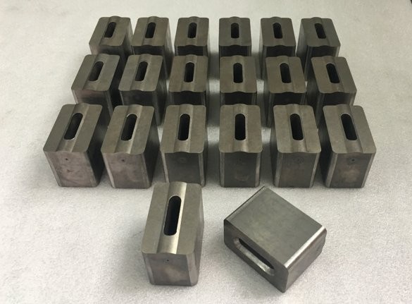
Pure tungsten carbide is non-magnetic; conventional WC-Co can interfere because the cobalt binder is ferromagnetic. For magnetic-material compaction, sensor-adjacent tooling or applications where metal pickup matters, we evaluate a WC-Ni or WC-Ni-Cr direction.
“Non-magnetic” is not a complete specification. The print should state the target relative magnetic permeability and the test method. We compare that target with the proposed nickel-binder grade and the required mechanical duty.
For a non-magnetic die review, send:
Nickel binders can change the impact and wear balance. A non-magnetic direction is therefore evaluated against the die route; it is not presented here as an automatic substitute for every WC-Co tool.
05 / From drawing to die insert
Drawing or CAD, workpiece, operation, mating assembly and failure evidence arrive together.
Separate impact, galling, hoop tension, recast damage, abrasion and magnetic interference.
Balance WC-Co or nickel-binder direction with the support, edge, bore and fit requirements.
Account for EDM removal, lapping direction, shrink assembly and final working surfaces.
Open geometry, capability or test-method questions are returned with the technical route.
06 / What to send
A complete package shortens technical review. If a controlled drawing is not yet available, send the worn part, scaled photos and dimensions so the missing definition can be identified.
Engineering references
These guides cover the die architectures, impact, galling, EDM and magnetic routes referenced on this page.
FAQ
A drawing is the strongest input. If it is unavailable, send a worn part, scaled photos, key dimensions, the mating assembly and the failure history. The reply will identify what still needs definition before a route can be confirmed.
State the target relative magnetic permeability and the test method. Also provide the magnetic powder or workpiece, orienting field, compaction pressure, impact condition, critical fits and finishing sequence. The WC-Ni or WC-Ni-Cr direction is then evaluated against those requirements.
Prototype and short-run work are part of the custom route. Minimum quantity and total scope are confirmed per drawing and manufacturing step; this page does not publish a universal minimum.
The route identifies whether the wire-EDM recast layer must be removed, when a casing or stress ring is used, and which working surface should be finished after assembly. These decisions stay tied to the approved drawing and fit intent.
Request a review
Include the forming operation, drawing or sample, mating assembly and what failed. We will review the die or mold route and return the open technical questions with the quotation.