Controlled drawing or CAD
Send PDF, DWG or STEP with revision, critical fits, mating housing or shaft, fluid path, retention method and any non-magnetic requirement.

Downhole and oilfield route
Carbidea supplies tungsten carbide wear parts for downhole and oilfield equipment, not complete tools or systems. Send a drawing, CAD model, sample or worn part for mud-motor radial bearings/bushings, MWD/LWD parts, mud-pulser rotor/stator parts, choke bean/seats, frac-pump seats/trim, wear rings, and erosion inserts or nozzles. We review fit, retention, erosion and impact before quoting in 1–2 business days.
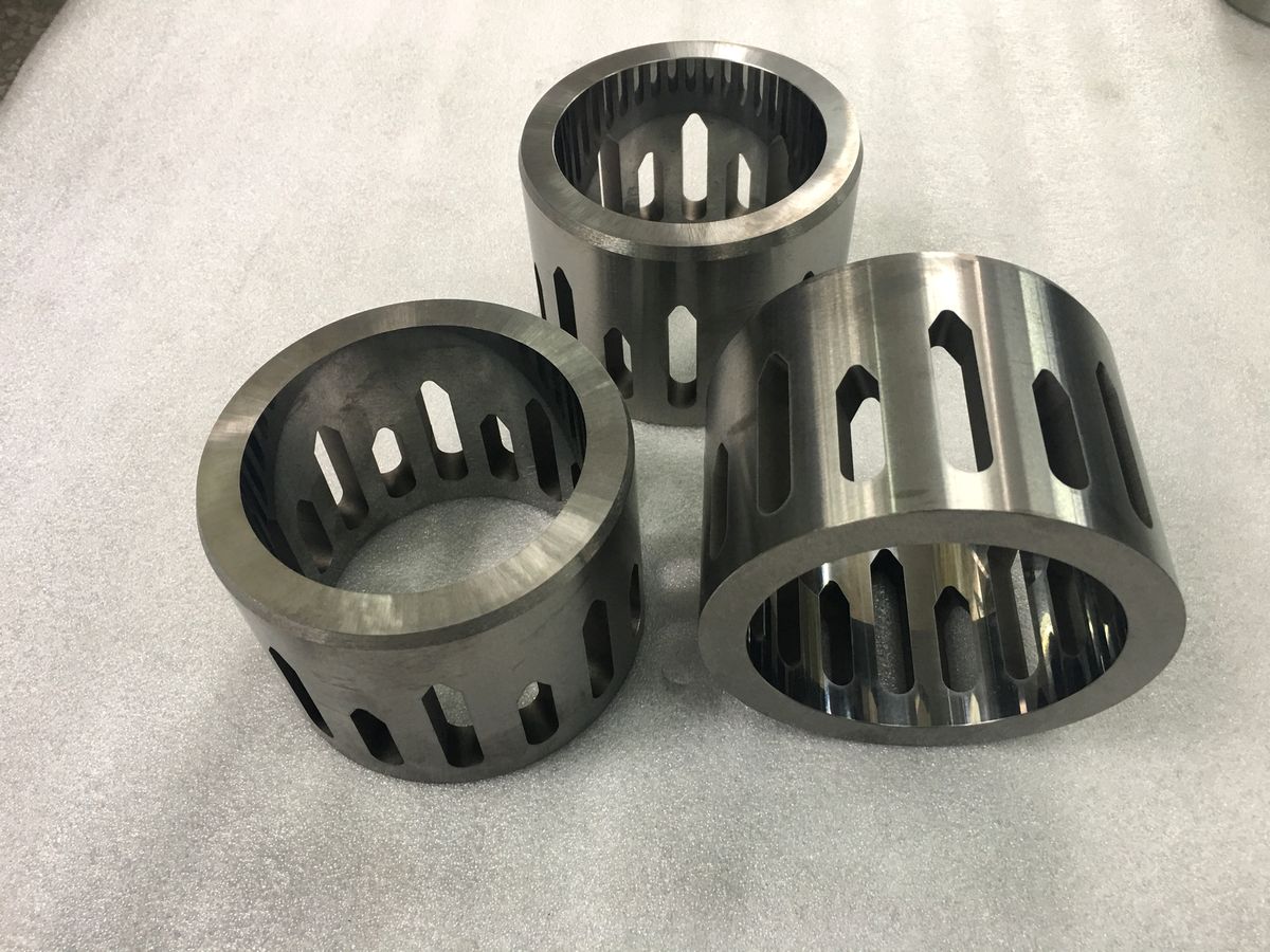
01 / Input record
The drawing defines the carbide part; the surrounding tool or equipment defines its support, retention, fluid path and consequence of wear. Both records are reviewed together before material direction or work scope is proposed.
Send PDF, DWG or STEP with revision, critical fits, mating housing or shaft, fluid path, retention method and any non-magnetic requirement.
Send scaled overview and close-up photos, key dimensions, the assembly context and the failure location. State what changed before removal.
Mating bore or shaft, locating faces, retention, running clearance and assembly direction.
Mud or process media, solids, pressure cycle, impact, temperature and previous service life.
Erosion path, impact origin, heat checking, cracking, clearances and the condition of adjacent parts.
02 / Wear-part register
This register is a review map, not a catalogue of complete tools. Geometry, material direction and manufacturability are assessed part by part.
| Carbide wear part | Typical failure | What the review checks | Material direction |
|---|---|---|---|
| Mud-motor radial bearing / bushing | Bore wear, shaft scoring, clearance growth and cracking | Radial load, running face, lubrication or mud path, retention and mating shaft condition | Wear / toughness balance by drilling duty |
| MWD/LWD wear component | Sensor-adjacent wear, erosion, impact damage or magnetic interference | Assembly interface, target magnetic behavior, test method and non-metallic wear path | WC-Co or nickel-binder direction after review |
| Mud-pulser rotor / stator part | Mud erosion, lost sealing clearance, impact chipping and heat checking | Flow path, mating profile, running fit, solids and the failed surface’s location | Fine-grain wear or tougher impact direction |
| Choke bean / seat | Wire drawing, bore washout, impact damage and lost sealing contact | Bore or taper, entry radius, pressure-drop path, seat pair and replacement access | Erosion-led or impact-led carbide route |
| Frac-pump seat / trim | Impact fatigue, edge spalling, sealing-face damage and erosion | Valve interface, impact cycle, sealing face, support and the mating component | High-toughness direction with wear balance |
| Wear ring | Diameter loss, clearance growth, galling and heat checking | ID, OD, finish direction, running gap, fluid path and mating material | Wear or nickel-binder direction by duty |
| Erosion insert / nozzle | Grooving, bore enlargement, impact loss and retention damage | Flow direction, solids, entry geometry, seating face and removal method | Abrasion-led carbide direction |
| Custom downhole wear part | Mixed wear, cracked or missing geometry and undefined mating condition | Drawing or sample, surrounding assembly, duty record and previous failure evidence | Selected after the governing failure is named |
No universal tolerance, minimum batch, service-life or material-grade value is implied by this register.
03 / Failure & control
Mud erosion, impact, heat checking and retention failure can damage the same surface in different ways. The material and geometry route follows the observed mechanism.
Review flow direction, entry geometry, solids, bore condition and the wear surface that governs replacement.
Review support, corner geometry, seating contact and repeated impact load before choosing the toughness direction.
Review the thermal cycle, mating material, surface finish and any evidence of cracking around the working face.
Review the sealing pair, contact band, flow path and replacement access for seats, beans and trim.
Review the running gap, shaft or housing condition and how adjacent wear changes the part’s function.
Review locating faces, shoulders, pins, shrink fits or other retention methods with the surrounding assembly.
GENERIC ASSEMBLY CHECK
04 / Non-magnetic route
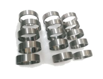
Some MWD/LWD or sensor-adjacent assemblies require a stated magnetic behavior. A conventional cobalt-binder route may not fit that requirement, so the target and test method must be defined before a material direction is proposed.
“Non-magnetic” is not a complete part specification. The page does not assume a grade or result. We evaluate whether a nickel-binder direction fits the wear, impact and assembly duty.
For a non-magnetic review, send:
A nickel-binder direction can change the wear and impact balance. It is reviewed against the equipment duty, not treated as an automatic substitute.
05 / Review route
Drawing, sample, mating interface, duty and failure evidence arrive together.
Mark flow, impact, sealing, locating and support surfaces against the surrounding tool.
Separate erosion, impact, heat checking, clearance growth and retention loss.
Balance tungsten carbide, nickel-binder or assembly requirements with the approved drawing.
Return open geometry, inspection, material or work-scope questions with the technical route.
Wear-part evidence board
These photographs show candidate carbide part formats. They do not present complete downhole assemblies or customer-specific equipment.
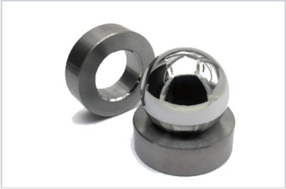
Part geometry and mating contact are reviewed from the drawing or sample; this photograph is not a complete valve assembly.
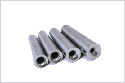
External and internal features are checked against the interface, retention method and finishing route.
06 / What to send
A complete package shortens technical review. If the controlled drawing is unavailable, send the worn part, scaled photos, key dimensions and enough of the surrounding assembly to explain support and retention.
Engineering references
These guides cover downhole wear, MWD/LWD parts, mud-pulser erosion and frac-pump seat failure.
FAQ
No. This route covers tungsten carbide wear parts only. Supporting documentation may describe the surrounding assembly, but complete tools, MWD/LWD systems, mud motors and frac pumps remain outside the supply scope.
Yes, as a starting record. Send scaled photos, key dimensions, the mating assembly and the failure location. The reply identifies which features still need definition before a route can be confirmed.
State the target magnetic behavior and the test method, plus the assembly, media, impact condition, fits, retention and finishing route. A nickel-binder direction is then evaluated against those requirements.
Prototype and short-run work are part of the custom route. Minimum quantity and total scope are confirmed per drawing and manufacturing step; this page publishes no universal minimum.
Request a review
Include the drawing or sample, mating assembly, service condition and what failed. We will return the technical route, quotation status and any questions still open.