Maintained by Carbidea · Last updated September 2026
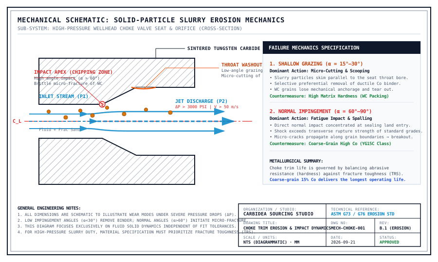
In severe-service flow control — including wellhead production chokes, frac manifold trim, and drilling choke manifolds — components must withstand differential pressures (ΔP) exceeding 3000 to 5000 PSI while throttling abrasive solid-particle slurries. In these extreme duties, valve seat failure rarely occurs as uniform abrasive wear. Instead, it is governed by two distinct fluid-solid interaction mechanisms: shallow grazing micro-cutting along restricted throat bores, and normal impact chipping at critical sealing land corners.
When high-pressure fluid carrying entrained proppant sand, formation quartz, or drilling fines encounters a choke orifice, potential energy (pressure) converts instantly into kinetic energy (velocity). Under a 3000 PSI differential pressure drop, local fluid velocities frequently escalate beyond 50 m/s (160 ft/s) at the vena contracta.
Per classical fluid erosion models, the kinetic energy (Ek) of an impinging solid particle scales with the square of velocity (Ek = ½ m v²), while volumetric erosion rates in turbulent slurry often scale with v2.5 to v3. Consequently, a modest increase in production flow rate drastically multiplies mechanical wear damage.
Along the parallel bore and downstream expansion of the choke seat or flow bean, fluid streamlines force particles to strike the tungsten carbide surface at shallow grazing angles (α ≈ 15°–30°). Under these conditions, failure progresses through a sequential two-phase mechanism:
At the leading seating land apex, throttling shoulder, and internal contour transitions, turbulent flow forces proppant particles to impact the carbide face at high angles approaching 90°. Here, the wear mechanism shifts entirely from ductile micro-cutting to brittle impact fracture:
A frequent specification mistake in severe-service trim design is choosing standard high-hardness tooling grades (such as YG6 / ISO K10, around 90 HRA). While ultra-hard grades excel against low-angle abrasive sliding, their low cobalt content (6%) yields low fracture toughness (KIC ≈ 9–10 MPa·m1/2). In severe throttling duty with dynamic particle pulsation, these brittle trims fail catastrophically by edge chipping within hours.
To maximize trim life in severe wellhead service, metallurgical formulation must prioritize fracture toughness and impact resilience:
| Grade Class | Binder & Grain Structure | Key Properties | Dominant Failure Resistance |
|---|---|---|---|
| Fine-grain tooling grade (YG6 / ISO K10) | 6% Co, Medium grain (1.6 µm) | 90.0 HRA | TRS 2600 MPa | Resists grazing abrasion only; highly prone to edge impact chipping. |
| Coarse-grain, high-cobalt grade (YG15C) | 15% Co, Coarse grain (2.5–4.0 µm) | 86.5–87.5 HRA | TRS ≥ 3200 MPa | Optimum Balance: High ductile cobalt network cushions normal sand impact, preventing crack link-up. |
| Nickel-Binder YN15 | 15% Ni-alloy binder, Coarse grain | 86.0–87.0 HRA | TRS ≥ 2800 MPa | Sour/Acidic Duty: Eliminates binder leaching in dissolved H&sub2;S, CO&sub2;, and completion brines. |
In sour production environments containing dissolved H&sub2;S, wet CO&sub2;, or heavy completion brines (such as zinc bromide or calcium chloride), chemical corrosion and physical erosion act synergistically. Standard cobalt binders are vulnerable to selective galvanic leaching. As the cobalt binder dissolves, the skeleton collapses under turbulent flow, magnifying the effective erosion rate by 5× to 10×.
For sour wellheads and subsea flowlines, our made-to-print trim components utilize corrosion-resistant nickel-binder carbide (YN series). The nickel-chromium binder forms an impervious passive film, preventing acid leaching and preserving the mechanical seat geometry.
Related Engineering & Sourcing Guides:
• Choke Valve Trim Specification Guide — Sizing, geometries, and manufacturing tolerances.
• A02-B00-C00 Apparent Porosity (ASTM B276) — How micro-void elimination protects fatigue life.
• Valve Seat Failure Analysis — Diagnosing washouts, thermal cracking, and cavitation.
• Erosion vs Corrosion Diagnostics — Distinguishing chemical attack from mechanical cutting.
• Carbidea Valve Parts for Oil & Gas — Custom choke seats, needle stems, flow beans, and wear sleeves.
Need custom choke trim engineered for severe slurry duty?
Send your engineering print (PDF, DWG, STEP) or worn sample details. We evaluate flow geometry, recommend an optimized grade formulation for the duty, and quote within 1–2 business days.
Request a Technical Quote